Bypass ratio


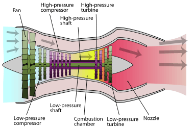
The bypass ratio (BPR) of a turbofan engine is the ratio between the mass flow rate of air drawn through the fan disk that bypasses the engine core (un-combusted air) to the mass flow rate passing through the engine core. For example, a 10:1 bypass ratio means that 10 kg of air passes through the fan for every 1 kg of air passing through the core.
The flow from the fan nozzle, rather than the core exhaust from the hot nozzle, produces most of the thrust in high-bypass designs. Bypass provides a lower thrust specific fuel consumption (grams/second fuel per unit of thrust in kN using SI units) for reasons explained below, especially at zero velocity (at takeoff) and at the cruise speed of the aircraft; also, the lower exhaust velocities reduce jet noise. Lower fuel consumption that comes with high bypass ratios applies to turboprops, using a propeller rather than a ducted fan.[1][2][3][4] High bypass designs are the dominant type for commercial passenger aircraft and both civilian and military jet transports.
Military combat aircraft usually use engines with low bypass ratios to compromise between fuel economy and the requirements of combat: high power-to-weight ratios, supersonic performance, and the ability to use afterburners, all of which are more compatible with low bypass engines.
Principles
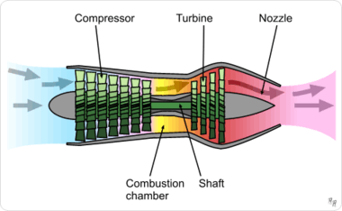
In a zero-bypass (turbojet) jet engine, all the air taken in is involved in combustion. The high temperature and high pressure exhaust gas is accelerated by expansion through a propelling nozzle produces all thrust. The compressor stage consumes all the mechanical energy produced by the turbine. In a bypassed design, conversely, the gas turbine component (or engine core) produces a large net positive power output because the turbine produces far more power than the compressor consumes, and this excess power drives a ducted fan that accelerates air rearward from the front of the engine. In a high-bypass design, the ducted fan, rather than combustion gases expanding in the nozzle, produces the vast majority of thrust. Turbofan engines are closely related to turboprop designs in concept because both designs de-couple the gas turbine's shaft horsepower from their exhaust velocities. Turbofans represent an intermediate stage between turbojets, which derive almost all their thrust from exhaust gases, and turbo-props which derive minimal thrust from exhaust gases (typically 10% or less).[5] Optimizing a gas turbine engine for shaft power output minimizes the exhaust pressure and temperature for maximum thermal efficiency within the limits of a Brayton cycle engine; conversely, pure jet designs require high pressure and temperature because they produce thrust by expanding exhaust gas through a nozzle. Bypass designs have two exhaust velocities, one passing through the core (combustion air) and air passing through the ducted fan alone (since in reality, most designs pass combustion air through the ducted fan first before passing into the compressor stage).[6]
Description
Turbojet engines are relatively inefficient as Brayton cycle engines because they directly convert thermal energy from combusting fuel into kinetic energy in the form of a high-velocity reaction jet directed through an expansion nozzle instead of producing mechanical power; therefore, pounds force or kilonewtons—not horsepower or kilowatts, as in propeller or turboprop engines—measure the power of a turbojet. Turbofans, conversely, are very efficient Brayton cycle engines because their gas turbine convert thermal energy from combustion into mechanical shaft power: the essential difference between a turbojet and turbofan gas turbine is that the turbine stage in a turbojet is designed to extract only a fraction of the available thermal energy in the high pressure and temperature exhaust, producing only enough mechanical energy to run the compressor stage as a net-zero mechanical energy system (ignoring very small mechanical outputs to run auxiliary equipment such as generators) and leaving a relatively high temperature and back pressure exhaust at the turbine exit for effective reaction propulsion. The gas turbine on a turbofan has additional turbine disks and stators, which are sufficient to convert most of the available thermal energy into mechanical work and leave an exhaust plume of greatly reduced temperature, pressure, and velocity. The back pressure at the turbine exit of a high bypass turbofan that maximally converts thermal energy into mechanical energy should be close to ambient pressure because the increased thrust derived from the ducted fan more than compensates the low direct jet propulsive efficiency of such an engine. In a high-bypass turbine engine, the gas turbine uses thermal energy from combustion to turn a ducted fan that slightly increases the velocity of a large amount of air.
Only the limitations of weight and materials (e.g., the strengths and melting points of materials in the turbine) reduce the efficiency at which a turbofan gas turbine converts this thermal energy into mechanical energy, for while the exhaust gases may still have available energy to be extracted, each additional stator and turbine disk retrieves progressively less mechanical energy per unit of weight, and increasing the compression ratio of the system by adding to the compressor stage to increase overall system efficiency increases temperatures at the turbine face. Nevertheless, high-bypass engines have a high propulsive efficiency because even slightly increasing the velocity of a very large volume and consequently mass of air produces a very large change in momentum and thrust: thrust is the engine's mass flow (the amount of air flowing through the engine) multiplied by the difference between the inlet and exhaust velocities in—a linear relationship—but the kinetic energy of the exhaust is the mass flow multiplied by one-half the square of the difference in velocities.[7][8] A low disc loading (thrust per disc area) increases the aircraft's energy efficiency, and this reduces the fuel use.[9][10][11]
The Rolls–Royce Conway turbofan engine, developed in the early 1950s, was an early example of a bypass engine. The configuration was similar to a 2-spool turbojet but to make it into a bypass engine it was equipped with an oversized low pressure compressor (the one closest to the front of the engine) which was centered inside a tubular nacelle (a ducted fan arrangement): the flow through the inner portion of the compressor blades went into the core while the outer portion of the blades blew air around the core to provide extra thrust. The bypass ratio for the Conway varied between 0.3 and 0.6 depending on the variant[12]
The growth of bypass ratios during the 1960s gave jetliners fuel efficiency that could compete with that of piston-powered planes. Today (2015), most jet engines have some bypass. Modern engines in slower aircraft, such as airliners, have bypass ratios up to 12:1; in higher-speed aircraft, such as fighters, bypass ratios are much lower, around 1.5; and craft designed for speeds up to Mach 2 and somewhat above have bypass ratios below 0.5.
Turboprops have bypass ratios of 50-100,[1][2][3] although the propulsion airflow is less clearly defined for propellers than for fans[13] and propeller airflow is slower than the airflow from turbofan nozzles.[11][14]
Engine bypass ratios
Turbofans, unless otherwise noted
References
- 1 2 Ilan Kroo and Juan Alonso. "Aircraft Design: Synthesis and Analysis, Propulsion Systems: Basic Concepts Archive" Stanford University School of Engineering, Department of Aeronautics and Astronautics. Quote: "When the bypass ratio is increased to 10-20 for very efficient low speed performance, the weight and wetted area of the fan shroud (inlet) become large, and at some point it makes sense to eliminate it altogether. The fan then becomes a propeller and the engine is called a turboprop. Turboprop engines provide efficient power from low speeds up to as high as M=0.8 with bypass ratios of 50-100."
- 1 2 3 Prof. Z. S. Spakovszky. "11.5 Trends in thermal and propulsive efficiency Archive" MIT turbines, 2002. Thermodynamics and Propulsion
- 1 2 Nag, P.K. "Basic And Applied Thermodynamics" p550. Published by Tata McGraw-Hill Education. Quote: "If the cowl is removed from the fan the result is a turboprop engine. Turbofan and turboprop engines differ mainly in their bypass ratio 5 or 6 for turbofans and as high as 100 for turboprop."
- ↑ Animated Engines
- ↑ "The turbofan engine", page 7. SRM University, Department of aerospace engineering
- ↑ "Fundamentals of Gas Dynamics", Robert D. Zucker, Matrix Publishers, 1977, pp 322-333
- ↑ Paul Bevilaqua : The shaft driven Lift Fan propulsion system for the Joint Strike Fighter page 3. Presented May 1, 1997. DTIC.MIL Word document, 5.5 MB. Accessed: 25 February 2012.
- ↑ Bensen, Igor. "How they fly - Bensen explains all" Gyrocopters UK. Accessed: 10 April 2014.
- ↑ Johnson, Wayne. Helicopter theory pp3+32, Courier Dover Publications, 1980. Accessed: 25 February 2012. ISBN 0-486-68230-7
- ↑ Wieslaw Zenon Stepniewski, C. N. Keys. Rotary-wing aerodynamics p3, Courier Dover Publications, 1979. Accessed: 25 February 2012. ISBN 0-486-64647-5
- 1 2 Philip Walsh, Paul Fletcher. "Gas Turbine Performance", page 36. John Wiley & Sons, 15 April 2008. Quote: "It has better fuel consumption than a turbojet or turbofan, due to a high propulsive efficiency.., achieving thrust by a high mass flow of air from the propeller at low jet velocity. Above 0.6 Mach number the turboprop in turn becomes uncompetitive, due mainly to higher weight and frontal area."
- ↑ "Rolls-Royce Aero Engines" Bill Gunston, Patrick Stevens Limited, ISBN 1-85260-037-3, p.147
- ↑ "Propeller thrust" Glenn Research Center (NASA)
- ↑ "Turboprop Engine" Glenn Research Center (NASA)