Spatial filter
A spatial filter is an optical device which uses the principles of Fourier optics to alter the structure of a beam of light or other electromagnetic radiation, typically coherent laser light. Spatial filtering is commonly used to "clean up" the output of lasers, removing aberrations in the beam due to imperfect, dirty, or damaged optics, or due to variations in the laser gain medium itself. This filtering can be applied to transmit a pure transverse mode from a multimode laser while blocking other modes emitted from the optical resonator.[1][2] The term "filtering" indicates that the desirable structural features of the original source pass through the filter, while the undesirable features are blocked. Apparatus which follows the filter effectively sees a higher-quality but lower-powered image of the source, instead of the actual source directly. An example of the use of spatial filter can be seen in advanced setup of micro-Raman spectroscopy.

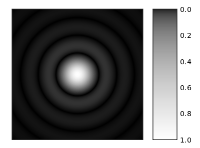
In spatial filtering, a lens is used to focus the beam. Because of diffraction, a beam that is not a perfect plane wave will not focus to a single spot, but rather will produce a pattern of light and dark regions in the focal plane. For example, an imperfect beam might form a bright spot surrounded by a series of concentric rings, as shown in the figure to the right. It can be shown that this two-dimensional pattern is the two-dimensional Fourier transform of the initial beam's transverse intensity distribution. In this context, the focal plane is often called the transform plane. Light in the very center of the transform pattern corresponds to a perfect, wide plane wave. Other light corresponds to "structure" in the beam, with light further from the central spot corresponding to structure with higher spatial frequency. A pattern with very fine details will produce light very far from the transform plane's central spot. In the example above, the large central spot and rings of light surrounding it are due to the structure resulting when the beam passed through a circular aperture. The spot is enlarged because the beam is limited by the aperture to a finite size, and the rings relate to the sharp edges of the beam created by the edges of the aperture. This pattern is called an Airy pattern, after its discoverer George Airy.
By altering the distribution of light in the transform plane and using another lens to reform the collimated beam, the structure of the beam can be altered. The most common way of doing this is to place an aperture in the beam that allows the desired light to pass, while blocking light that corresponds to undesired structure in the beam. In particular, a small circular aperture or "pinhole" that passes only the central bright spot can remove nearly all fine structure from the beam, producing a smooth transverse intensity profile, which may be almost a perfect gaussian beam. With good optics and a very small pinhole, one could even approximate a plane wave.
In practice, the diameter of the aperture is chosen based on the focal length of the lens, the diameter and quality of the input beam, and its wavelength (longer wavelengths require larger apertures). If the hole is too small, the beam quality is greatly improved but the power is greatly reduced. If the hole is too large, the beam quality may not be improved as much as desired.
The size of aperture that can be used also depends on the size and quality of the optics. To use a very small pinhole, one must use a focusing lens with a low f-number, and ideally the lens should not add significant aberrations to the beam. The design of such a lens becomes increasingly more difficult as the f-number decreases.
In practice, the most commonly used configuration is to use a microscope objective lens for focusing the beam, and an aperture made by punching a small, precise, hole in a piece of thick metal foil. Such assemblies are available commercially.
Spherical waves
By omitting the second lens that reforms the collimated beam, the filter aperture closely approximates an intense point source, which produces light that approximates a spherical wavefront. A smaller aperture implements a closer approximation of a point source, which in turn produces a more nearly spherical wavefront.
See also
- Köhler illumination, which applies spatial filtering to incoherent light for microscopy
- Pinhole camera
References
- ↑ "Understanding Spatial Filters". Edmund Optics website. Edmund Optics. Retrieved 13 January 2014.
- ↑ "Spatial Filters". Newport website. Newport. Retrieved 13 January 2014.